| Version 12 (modified by , 8 years ago) ( diff ) |
|---|
Overview
The Buchla 700 was a synthesizer released in 1987. It was conceived and built by Donald Buchla together with Lynx Crowe, who wrote the firmware for the 700. Some years ago Lynx kindly allowed Aaron Lanterman to release the source code on his website: http://lanterman.ece.gatech.edu/buchla700/. While our modifications are in the public domain, Lynx's request still applies to the underlying original code. Please respect that.
The Buchla 700 was a 12-Voice polyphonic synthesizer using frequency modulation, wave shaping and wave shape interpolation to create its sounds. In contrast to many instruments of its time it did not use a traditional keyboard as input, but an array of touch sensitive membrane keys.
In addition to the inbuilt LCD display, an external monitor could be connected for editing of sounds.
This is a walkthrough some simple functions which might be of interest without sound.
Starting the Emulator and MIDAS
By switching to the directory and running ./buchla in the terminal or simply by clicking on the icon, you can start the emulator. Three windows will appear: One emulates the main graphic display (which will still be blank), one the smaller LCD display (showing "Buchla 700 -- BIOS/FIRMWARE by D.N. Lynx Crowe") and one the debug terminal (showing an orange cursor). Make sure the debug console is in focus and then press "r". "Buchla 700 BIOS / Debug PROM" should appear and there should be a prompt: "ROMP:".
Type "go $10000" to load the MIDAS operating system. The graphic display should now show a menu and the LCD display should show faders.
Overview of key shortcuts
The emulator is usable via a combination of mouse and keyboard. It was possible to connect an actual mouse to the 700’s serial port, so even if it might be somewhat unusual by modern standards we have kept it. Approached from a modern perspective the interface of the 700 needs some adjustment. Certain keys have different values in different situations and sometimes even function differently depending on which area the mouse is hovering over.
The keyboard Layout is as follows:
| Emulator | 700 |
| Keys 0 - 9 | Data entry keys 0 - 9 |
| Keys 'a' - 'n' | Move fader 1 - 14 up |
| Shift + keys 'a' - 'n' | Mover fader 1 - 14 down |
The mouse functions as follows:
| Emulator | 700 |
| Left mouse button | Select |
| Right mouse button | Escape to main menu |
The 700 hundred had 10 data entry keys counting from 0 - 9. These are used whenever numerical data needs to entered. Keys 8 and 9 have the additional function of being able to increment/decrement numbers and at other times toggle functions. We have emulated these using the numbers on your computer keyboard, 0 - 9 being mapped to the corresponding data keys, with 8 and 9 being used for incrementing and decrementing.
The membrane faders on the top half of the keyboard were used for direct manipulation of parameters. Each fader has a corresponding segment in the LCD display containing the name of the assigned parameter and a vertical bar representing the amount applied.
In future releases, a midi mapping to the faders will be possible, but at present they are emulated by keyboard alone. Keys ‘a’ to ’n’ are assigned to the faders, where a normal keypress emulates the fader being pushed upwards and a keypress with shift emulates it being pressed down
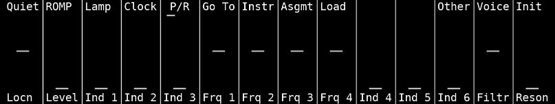
The layout of the membrane keys is as following:
[Image of membrane key layout]
Midi Configuration
It is possible to control the Emulator with a midi keyboard. Currently, it must be started from the command line with the extra argument ‘-m’ and desired midi channel. An example command for using it with MIDI channel 1 is:
./buchla -m 1
Librarian
For the Librarian to work we need to start the emulator slightly differently. After running "./buchla" but before typing "go $10000", type "midas" in the debug console. This loads MIDAS into the memory and initialises the disk drive. Without doing this, the patches will not be saved. The start MIDAS with "go $10000".
Score Editor
The Score Editor allows you to record and arrange performances. It is possible to record a MIDI Sequence in the emulator. To do this, hover the cursor over the green star of the groups in the GROUP/INSTRUM row. Pressing + (9) once will change it to yellow and a second time will change it to red (Track is armed). On the bottom of the screen select Recrd. Then, to start recording select Clock at the top of the screen. Now the played MIDI notes will be shown in the score.
If you do not have a MIDI controller, it is still possible to draw notes. At the top of the screen click on "Src Local". In the appearing menu, select "Step". Arm one of the groups by hovering over the green star and pressing + (9) twice. Select "Recrd" at the bottom of the screen. Then in the top right corner click on "Note Edit" and select "Begin Nat" from the menu. Now you can draw MIDI note on events by clicking (only once!) on the staff (right of the line in the center) at the desired pitch. The Score Editor will start scrolling and reappear with the drawn note. "Begin Nat" will have changed to "End Note", allowing you to set the end of the MIDI note by clicking on the desired spot.
Instrument Designer
The Instrument Designer lets you edit the "Functions"/"Envelopes" for different parameters. The functions (displayed on the graph) are made up of individual points, so called breakpoints, which are interpolated linearly. Clicking on the preview at the top of the screen ("Frq 1", "Frq 2", etc.) allows you to select the function of the parameter you would like to edit.
To edit the last breakpoint: Click on the function graph (or press 'e') and the last breakpoint will become red and not be connected to the last anymore. Now click to the desired position you would like to change it to and the function will be redrawn.
To add a breakpoint: Press + (9) and the last breakpoint will become red, but will still be connected. Now click on the desired position you want the new breakpoint to have.
To remove the breakpoints: Hover your mouse over the number in the "Pt " box underneath the graph. Use the number keys to enter the breakpoint you would like to delete from, e.g. "05". The 5th and all following breakpoints will be deleted.
Waveshape Editor
The Waveshape Editor allows you to edit the transform function for the oscillator. What looks like a waveform is in fact an array of 254 values which are scanned by the wave generated by the frequency modulation setting. To understand this better, imagine a sine wave oscillating between 0 and 253, it will count from 0 until 253, back down again and repeat. Instead of playing the actual waveform directly a value is used to lookup the value stored in the waveshape table. In our example the sine wave would look up all values from 0 until 253 and then from 253 until 0 and repeat. This way, if you draw a diagonal line from bottom left until top right, the scanning waveform will be played unaltered.
The Waveshape Editor shows you the current wave shape being used. Click on a point in the wave or hover over a point and press ‘e’, this will toggle the edit mode. If you move the mouse up or down and wait a second or two for the screen to refresh you will see you have changed the value of single point. To exit the edit mode click or press ‘e’ a second time.
Most of the time you will of course want to manipulate more than a single point. For this, move the mouse cursor over the wave shape and press + (9) or - (8). This will change the “Width” setting in the control part of the screen. You can select "Width 0" until "Width 7" and another option "Interp". The "Width" options allow you to “bend” multiple points, 0 being only one point and 7 being the entire wave shape. "Interp" lets you draw the wave shape free hand.
Tuning Tables, Patch Editor, Assignment Tables, Sequence Editor
These screens might be fun to explore, but have limited effect in this version without the sound engine.
Attachments (1)
- lcd.png (16.9 KB ) - added by 8 years ago.